-
Update Agent (GT devices)
-
Device Updater (X4, LWTS+, BDX, & GTX Devices)
-
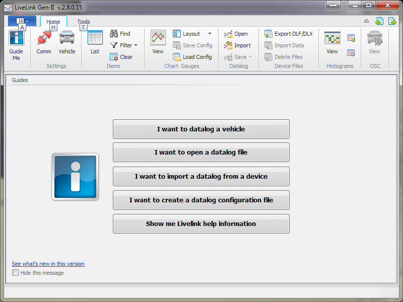
LiveLink Gen II
-
Advantage III
-
TeamViewer
- Add Button
Bully Dog Update Agent (Updater for GT devices)
*To avoid issues with downloading the Update Agent, install with Internet Explorer.
To install the Update Agent click here
All software including the Update Agent is not Mac compatible. A Windows-based PC will be required.
If your Tuner for a Toyota gets a T999 Update Agent Error it means that there is a connection issue with the update agent to our server.
Verify any Anti-Virus programs are off, or disabled and continue to retry the update until the server reconnects and allows an update. (If you are unsure how to disable your Anti-Virus program please refer to your user manual for that software.
If the problem persists, please contact our Technical Support Team using the "Contact Support" button below. Please be sure to have your device and access to a PC computer with internet access.
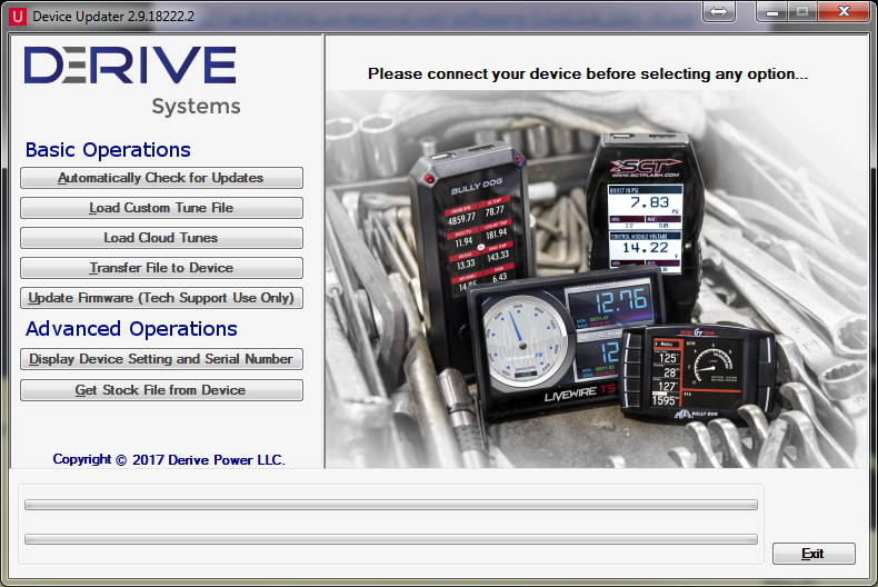
Device Updater
Click here to download the Device Updater.
Make sure all devices are unplugged during the install process.
All software including the Device Updater is not Mac compatible. A PC with Windows Vista/7/8/10 will be required.
MAKE SURE YOU ARE USING A USB CABLE WITH DATA TRANSFERABILITY. NOT A CHARGING-ONLY CABLE. (The included cable is a data cable.)
-
Installing and Operation Definitions
-
Device Not Recognized
-
Window not Fully Displaying Content
-
Getting the Stock File from the Device
-
Windows Vista Exception Errors
- Add Button
Click here to install the Device Updater.
Automatically Check for Updates
Used for updating your device. You will also find here the device Part Number, Serial Number, Firmware version, and your Vehicle Information (You must read "Vehicle Info" or "Tune" your vehicle in order for your vehicle Information to display while checking for updates.)
Load Custom Tune File
Used to Add/Remove custom tune (.CEF) files. You can also rename a custom tune file here. The "Browse" button will allow you to browse to a specific location on your computer to find and load your custom tune files. The "Locate Custom Tunes" button will allow you to locate all .CEF files stored on your computer that are not stored within a folder. Example: .CEF (Custom Tune) files that you have stored in your downloads folder or your desktop will display right away when you select the "Locate Custom Tunes" button.
Load Cloud Tunes
Used to download your cloud custom tune file from the cloud and load the file directly to your device. (The custom tune will also remain/be available on
Transfer File to Device
This option is used to transfer saved Livelink Data Log configuration files to your device for on-device data logging.
Update Firmware (Tech Support Use Only)
Used by Tech to upload firmware to the device.
Display Device Setting and Serial Number
Here you will find the device part number, Married Count, Married status (if the box is checked, that means the device is married), Tune Revision, EEC Type, Serial#, and the device Firmware. There is a "Copy to Clipboard" button which when clicked, copies all of the shown information to your clipboard for you to then paste where you'd like. You'd usually copy and paste this information to send to our tech team in most cases.
Get Stock File from Device
You'd click this button to save a copy of the device files which could include your vehicle stock calibration (The stock calibration is saved to your device during the tuning/flash process). The file will save as a .BEF File which includes your device serial number. Example: BD01234567890_20190404170205_Saved_NEW
Running our Program as an Administrator
On many PC's you may be required to run the program as an administrator. To do this follow the below directions:
- Right-click on the device updater's icon and choose Properties.
- Click the Advanced button under the Shortcut tab in the Properties window.
- Check the “Run as administrator” box and click OK, and then OK again to close out of the Properties screen.
- Run the program.
This is typically a device driver issue that occurs when a device is plugged into your computer for the first time without downloading the Device Updater first.
First and foremost; MAKE SURE YOU ARE USING A USB CABLE WITH DATA TRANSFERABILITY. NOT A CHARGING-ONLY CABLE. (The included cable is a data cable.)
Easiest Solution:
Step 1. Disconnect your device from the computer (Do not reconnect the device until step 4)
Step 2. Completely Uninstall the Device Update software from your computer
Step 3. Reinstall the Device Updater software, the device drivers are installed in the same instance as the Device Updater.
Step 4. Reconnect your device to see if the problem has been resolved. (For GTX- plug in the VIM, NOT the head unit)
Advanced Solution: Load them manually
Manually loading the drivers can be done quickly and easily if you follow these simple steps.
You will need to know if you have a 32-bit or 64-bit version of Windows. Click HEREto determine which version you have if you don't know.
Step 1: Choose the correct driver files below and save them to your computer’s desktop.
64-Bit Driver Download 32-Bit Driver Download
Step 2: Locate your computer’s Device Manager. Right-click the SCT MB103 Device. This is the name of your device when the drivers are not properly installed yet.
Step 3: Select the Update Driver Software option for the device, then browse your computer and point to the driver files you downloaded earlier.
Step 4: Select “OK” and then select “Next” – That’s it! You’re all set!
If the device still does not communicate with your PC, give us a call with the device, and access to a Windows PC to further troubleshoot with one of our Technical Support Agents
- Right-click anywhere on your "desktop" and select "personalize"
- Click on "Display" at the lower left corner.
- Select "Smaller - 100% (Default)" and click "apply". Your computer is probably set to Medium or Larger.
- The computer will tell you that these changes will not take place until you log off and back on. Save what you are working on and log off windows and back in.
- When you open the SCT Device Updater now all of the buttons should be visible.
For certain things, Support may require the stock file to be emailed to them. In order to get the stock file, you will need our Device Updater software. Please follow the instructions below:
- Click here to get the Device Updater. Note: You will need a Windows computer to do this as it is not Mac compatible.
- Once the Device Updater and SCT drivers have finished installing, plug your device into the computer.
- A pop-up should appear to notify you of a new device and automatically start to install. You may need to allow it to install but most machines will do it automatically.
- After that installation completes open the Device Updater software (shortcut may be on desktop – it’s a red square with a white ‘U’ in the middle)
- Click on ‘Display Device Info and Serial Number’ (the second to last button)
- If your serial number is displayed, your device is connected and communicating properly.
- Click back.
- Click ‘Get Stock File from Device’.
- Click ‘Browse’.
- Browse to your computer's Desktop.
- Click ‘Select Folder’.
- A pop-up stating the files were saved will appear. Click ‘OK’.
- You should see a white icon on your desktop with your device's serial number as the name, and .BEF as the file extension.
- Attach this file to your email and send it to support@sctflash.com.
If you experience difficulties pulling the files off your device don’t hesitate to give our Tech Support a call. We’re open Mon-Fri from 9:00 AM – 6:00 PM EST. Make sure you have your PC with an internet connection and TeamViewer downloaded and running so we can remotely connect to your PC and assist you as quickly as possible. Download TeamViewer here.
Device Updater on Vista
- System.Net.WebException: The underlying connection was closed: An unexpected error occurred on a receive
- System.ComponentModel.Win32Exception: The client and server cannot communicate, because they do not possess a common algorithm
This issue is a result of TLS 1.1 & 1.2 not being enabled on the Vista operating system. We'll need to enable this in order for the Device Updater to function properly.
- Open Windows Update and ensure you have applied all Critical and Important updates for Windows Vista through when it was end of life.
- Click the Download button next to either “2018-05 Security Update for Windows Server 2008 for x86-based Systems (KB4056564)” or “2018-05 Security Update for Windows Server 2008 for x64-based Systems (KB4056564)” depending on whether it's Windows Vista 32-bit or 64-bit. If you're unsure of the version of Windows Vista, you can right click on My Computer in Windows Explorer and it will show in the details.
- Run the windows6.0-kb4056564-v2-x86_1cf1b27424b4017e5f1341d88b42c463a62e1ac8.msu (or x64) file that is downloaded and follow along the prompts to install the patch.
- Restart the computer
- Download this .reg key: vista-tls-1.1-1.2-update.reg (Right click > Save link as…)
- Double click the .reg key and allow it to merge into the Windows registry (For the curious, this will remove version-specific information from the CRYPTO\TLS1.1 and CRYPTO\TLS1.2 keys allowing the options to display in Internet Options)
- Open up Internet Options from your Control Panel or from within Internet Explorer by clicking the gear icon and selecting Internet Options
- Click the Advanced tab
- Scroll all the way down and check the boxes next to TLS 1.1 and TLS 1.2
- Click Apply & OK
Livelink Gen-II
Click here to download the Livelink Gen-II.
Make sure all devices are unplugged during the install process.
All software including Live-Link is not Mac compatible. A PC with Windows Vista/7/8/10 will be required.
 +
+
-
Setting up a Histogram
-
How to Validate PIDS
-
Creating a DLX File
- Add Button
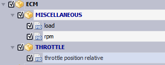
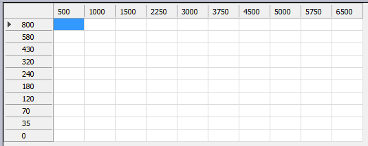
1. The first and most critical step is selecting the correct PIDs for the histogram you would like to create. You need to know what PIDs will correspond to the to the table you are looking to create a histogram for. In this example, we are doing a Load with Failed MAF Table as pictured.
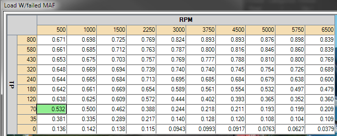
The X-axis is RPM, the Y-Axis is Throttle Position Relative in counts, and the Z-Data is Load for the table above. During our PID selection screen we are going to grab these PIDs. You may select additional PIDS, but you must select these PIDS so that these channels can be utilized in our histogram.
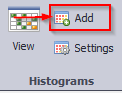
Once you have selected the PIDs, you can configure the data log and begin creating the histogram. In the top menu bar click Add in the Histograms area. When the Histogram box pops up, click Add New.
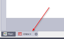
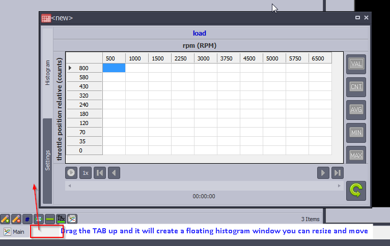
A new tab at the bottom left of your screen will appear and you will be on the Histogram Settings tab. When we save this histogram later, it will change from “new” to the name you save it as.
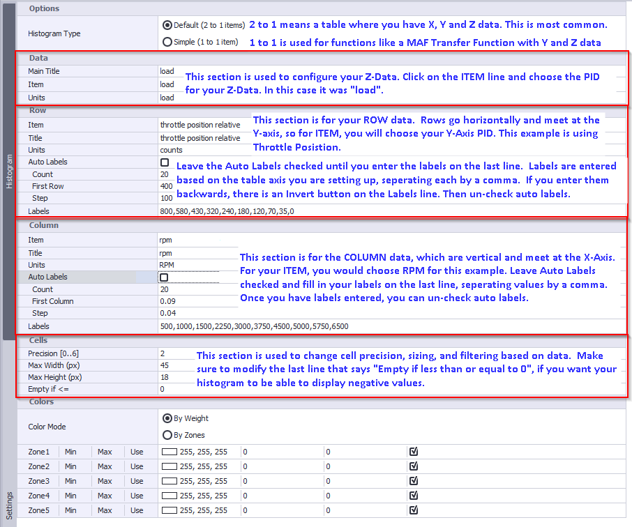
Now it's time to start configuring our settings of the histogram. Follow the instructions on this image.
Now on the LEFT side of the page, click on Histogram and check if your table matches the table in Advantage. It should be the same size/dimensions as the original table, in this case the Load with Failed MAF table.
Switch back to SETTINGS using the left side tab, and click SAVE As… at the bottom right corner to Save your histogram for later use.

A histogram can be created before logging, or even after logging if you have already data logged the correct pids for your histogram. You can also grab the small tab at the bottom left and drag it up, to create a floating histogram window on your chart view.
-
You can filter your histogram to display different ways using the buttons on the right of the Histogram.
VAL = Value = Displays only the current value for the spot you are at in time line.
CNT = COUNT = Displays how many time each cell was “hit” to collect data. This is helpful to filter out cells that were not hit frequently to collect reliable data.
AVG = AVERAGE = Displays the average value for each cell up to that point on the timeline. This is the most commonly used button.
MIN = MINIMUM = Displays the lowest value for each cell that data was collected up to that point in the timeline.
MAX = MAXIMUM = Displays the highest value for each cell that data was collected up to that point in the timeline.
With Livelink GenII open:
- Select I want to datalog a vehicle
- make sure your tuning device is plugged into the PC, and the vehicle
- Start the engine when it tells you
- select check Communication on LLG2
- Then choose vehicle info in the lower right part of the LLG2 screen
- If you have never validated Items on this vehicle before select Validate all items
- then choose select items in the lower right of the screen
- Once validation is complete it will pull up a list of all the PIDs and DMRs available for that vehicle
- Select the items you want to datalog then select configure datalog
This video will show you how to create and load a DLX file to your device for monitoring and data logging.
Advantage III
Click here to download Advantage III.
Note: Sometimes certain browsers will not allow the download by clicking the link above. If that happens to you, just copy and paste the following into the address bar: https://cdn.sctbullydog.com/sctfiles/AdvantageIII/AdvantageIII.exe
Make sure all devices are unplugged during the install process.
All software including Advantage III is not Mac compatible. A PC with Windows Vista/7/8/10 will be required.
-
Additional Info
-
Vehicle & Tuning Index
-
Database Error 0
-
Advantage Direct Flash
- Add Button
Basic Info:
Advantage III is Derive Systems custom tuning software suite.
Currently, Advantage supports most 1996 and newer Ford, GM, and DCX applications. There are exceptions, but for the most part, it covers a wide variety. There is even support from some older non-OBD2 vehicles.
Custom tuning dealers around the world use Advantage to create custom calibrations for various vehicles.
Advantage III is essentially a graphical user interface used to change the OEM calibration. We can modify thousands of parameters such as spark, fuel, boost, torque management, and transmission tuning, etc.
Value Files:
|
Value Files are very helpful and can help save time when tuning a car. Value Files are saved tuning values. Derive Systems provides many good Value Files with Advantage, and they are updated on occasion.
|
Lost and/or Damaged Dongles:
Lost and damaged Dongles can be replaced for $50. Simply call and connect with our sales team to purchase a new Dongle today.
Download: https://cdn.sctbullydog.com/sctfiles/AdvantageIII/AdvantageIII.exe
A/F
Air to fuel ratio. An air to fuel ratio of 14.64 to 1 is used by manufacturers
as the optimum setting for minimizing emissions. This you will see expressed
as 14.64, but what it means is, there is 14.64 parts of air to one part of
gasoline. The ‘parts’ mentioned is generally weight and another way of saying
weight is ‘mass’. Optimum wide open throttle A/F is anywhere from 12.5 to
13.5 for a naturally aspirated vehicle and from 11.5 to 12.0 for a power adder
vehicle. The optimum A/F ratio is discussed in this book.
AC
Air conditioning.
ADVANTAGE
“Advantage” is the name of the tuning software released by Derive Systems
ACT
Air Charge Temperature sensor. This is a crucial sensor that measures
and reports to the PCM the actual temperature of the air going into the engine.
This sensor provides input that may modify how much timing and fuel go into
the engine. It is VERY important in a car with a supercharger or turbocharger
that the ACT be located after the blower and/or intercooler. In other words,
you will want the ACT to measure the temperature of the air after the air has
been compressed. This is critical because it is a law of physics that whenever air
is compressed, it is heated. SCT takes this into account in the value files and
base files for a blown car. Not locating this sensor after the blower could result
in severe engine damage. This also can be referred to as the IAT sensor.
Ambient – This is the air temperature that the engine will be ingesting. If the
car is outside on a 75º day, then the ambient temperature is 75º.
Batt
The car’s battery voltage (normally 12 volts DC.)
BAP
Barometric air pressure sensor. Used on older EEC IV cars to measure
barometric pressure of the atmosphere. This was eliminated in later models.
This data is now inferred from the MAF readings.
Boost
This is simply a measurement of pressure in pounds per square inch. It
applies to a blown car and is normally measured in the intake manifold. Boost
by itself really doesn’t mean much, except as a rough guide as to how much
extra air is being forced into the engine and is being heated in the process. An
engine is a big air pump. The more airflow it can generate, the more power the
engine will make.
CCS
Converter Clutch Solenoid used in an automatic transmission to control
lockup of the clutch that is inside the torque converter.
CEL
Check Engine Light. This a light that comes on when there is an emissions
failure or a sensor failure. If this light comes on, then a diagnostic trouble
code has been set and action needs to be taken to resolve this issue. This can
also be referred to as an SES light, Service Engine Soon.
Closed Loop
When the engine is using input from the oxygen sensors and the
MAF to control the engine to 14.64:1 air-fuel ratio.
DCL
Data Communication Link –This is a protocol used in later EEC IV
processors that allow viewing of some real-time sensor data.
DIS
This is a Distributor-less Ignition System. This type of ignition system
has no distributor but only has a small number of magnets on the crankshaft,
exactly half the number of cylinders the engine has. This system needs a camshaft
sensor to properly synchronize the ignition system. This type of system
was mainly used on 3.8L SuperCoupes and some 2.3L Mustangs/Rangers.
EEC, ECM, ECU
Electronic Control Module/Unit, the car’s computer or
PCM.
ECT
Engine Coolant Temperature sensor. This is a crucial sensor that measures
and reports to the PCM the actual engine coolant temperature in the
engine. This sensor provides input that may modify how much timing and fuel
go into the engine.
EDIS
Electronic Distributor-less Ignition System used in later Fords. This is
an ignition system used in Ford vehicles that do NOT use a distributor. This
type of ignition system uses a 36-1 tooth wheel on the crankshaft to pickup
engine speed.
EFI
Electronic Fuel Injection.
EGO
Exhaust Gas Oxygen Sensor – also referred to as a 02 sensor. This sensor
provides feedback as to whether or not the system is either rich of 14.64:1
air-fuel ratio, or lean of 14.64:1 air-fuel ratio. It does not, and cannot provide
data as to the actual air-fuel ratio.
EGR
Exhaust Gas Recirculation – This is an emissions component that recirculates
exhaust gas into the engine. This reduces combustion temperatures and
at the same time reduces nitrogen based emissions from the vehicle. It is only
used at part throttle on a warm engine. It is shut off by the PCM at WOT. The
EGR valve does not hurt performance at all and even increases fuel economy.
EGT
Exhaust gas temperature.
EPC(S)
Electronic Pressure Control Solenoid. This is a solenoid in an automatic
transmission that regulates line pressure. This can also be referred to as a TV
solenoid.
EVP(S)
EGR Valve Position Sensor. This provides feedback to the PCM as to
what level the EGR valve is operating at.
HEGO
Heated Exhaust Gas Oxygen Sensor, also referred to as a 02 sensor.
This sensor provides feedback as to whether or not the system is either rich of
14.64:1 air-fuel ratio, or lean of 14.64:1 air-fuel ratio. It does not, and cannot
provide data as to the actual air-fuel ratio.
HEI
High Energy Ignition.
IAC
Idle Air Control. This valve uses feedback from the PCM to automatically
vary the amount of air going into the engine at idle to control idle speeds
as set by the PCM. This can also be referred to as an ISC valve.
IAT
Intake Air Temperature, see ACT above.
IMRC
Intake Manifold Runner Control - It is a device that allows the intake
manifold to switch from a long runner to a short runner and vice-versa. Typically,
a longer runner makes more low RPM torque and a shorter runner makes
more peak horsepower (HP). Having two runner lengths allows a broader, flatter
torque curve. Normally, the longer runner creates more swirl in the combustion
chamber and therefore the combustion chamber becomes a faster burn
chamber, requiring less overall timing for peak HP. When the IMRC opens
the shorter runner is utilized. This results in a slower burn rate combustion
chamber and requires more timing to produce peak HP. The PCM controls the
amount of spark that gets added when the IMRC opens.
ISC
Idle Speed Control, see IAC above.
KAM
Keep Alive Memory. This is an area in the PCM’s memory where data
is stored that will allow the PCM to adapt and change settings to allow for
changing conditions. This area is kept powered up even when the vehicle is not
running.
Load
Load can also be called volumetric efficiency. It is usually expressed in
a percentage, such as 50% load. Load or volumetric efficiency is actually the
measurement of how much air is flowing into the engine. If a 4.6L engine
sucks in 4.6L of air in two engine revolutions (it takes two engine revs for all
the cylinders to go through their different strokes) then it’s load is 100%. If it
only sucks in 2.3L of air, then it’s load is 2.3/4.6 or 50%. On a blown car, you
can force more air into the engine than it’s displacement, so load will go above
100%. Load is VERY important because as you will learn, load is used on
many of the tables for a variety of critical engine controls. Load is calculated in
the PCM based on input from the mass air meter.
You can calculate load mathematically:
((MAF reading (lbs/min) X 2) / (RPM X 8)) / engine_displacement
Here’s an example: ((40 lbs min X 2) / (6000 X 8) ) / 0.00155 = 1.075, or .5%
LTFT
Long-term fuel trims. These are values that are stored in the PCM that
tell the computer the trends for correction made by the PCM, using feedback
from the oxygen sensors (EGO/HEGO) to correct for conditions that cause the
fuel control to vary from 14.64 A/F at idle and part throttle.
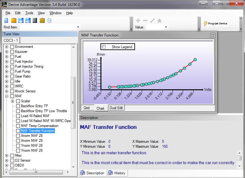
MAF
Mass Airflow Sensor. This is the most critical sensor in a car. It directly
measures airflow with an electronic hot wire sensor. The sensor resides in a
small ‘sample’ tube that is in the incoming air path. The sample tube size is
calculated to be a certain proportion of the larger inlet tube. The wire is heated
to a specific temperature and the PCM tries to keep it at a certain target temperature.
As airflow increases, the sensor cools, the PCM responds by adding
more voltage to keep the sensor’s temperature constant. The meter can output
up to 10 volts or more, but the PCM will only acknowledge a maximum of 5v.
As engine airflow increases, the voltage increases signaling more air to the PCM.
If the meter is of insufficient capacity and goes past 5v, this is called pegging or
saturating the meter. We will discuss this in detail later. The PCM determines
the air mass from a software function in the PCM. This is called the MAF
transfer function. The transfer function is a series of points on a graph that
shows a specific air weight at 30 voltage points. There is a lengthy discussion of
this in this book.
MAP
Manifold Absolute Pressure sensor. This measures the pressure inside
the intake manifold.
MIL
Malfunction Indicator Lamp – the same as a check engine light.
MLPS
Manual Lever Position Sensor. This is a sensor on an automatic transmission
that tells the PCM what position the gearshift lever is in. This is also
referred to as a TRS, Transmission Range Sensor.
NA
This means naturally aspirated. A power adder (nitrous or blower) is not
being used.
OBD
On-Board Diagnostics.
O2
Oxygen.
Open Loop
When the engine is running without direct input from the oxygen
sensors.
PCM
Powertrain Control Module, the car’s computer.
PCV – Positive Crankcase Ventilation.
PIP – Profile Ignition Pickup. This sensor is located either in the distributor (if
so equipped with one) or is calculated from a crankshaft position sensor. The
PIP signal is used by the PCM to determine engine timing and injector operation.
Power Adder – Either a supercharger, turbocharger or nitrous oxide. Used to
provide more air and fuel to the engine.
PSI
Pounds per square inch. This is a measurement of pressure that can also
be designated with a ‘pound’ sign such as 5#.
ROM
Read Only Memory.
SEFI
Sequential Electronic Fuel Injection.
SPOUT
Spark Output signal. This is a signal that is output by the PCM to
either the TFI module (on distributor cars) or the EDIS/DIS module. This
signal contains the information required for the module to output the spark at
the correct time.
STFT
Short term fuel trims. A ‘trim’ is a correction that is applied to a setting
in the engine. STFTs are used at idle and part throttle. They are usually
expressed as either a positive or a negative number. A negative number means
the car is too rich and the PCM is attempting to ‘trim’ a percentage of fuel out.
A positive number means it is running too lean and the engine is adding fuel. A
STFT of (-10%) means that the PCM is pulling 10% fuel to get the engine to
operate 14.64 A/F.
Stoichiometric or Stoich
This is the chemically correct air-fuel ratio, typically
14.64:1 for gasoline.
Target A/F
We will refer to target A/F as the value we are targeting for when
we are tuning the engine.
TDC
Top Dead Center. This is a measurement of the piston location in
degrees of crankshaft rotation. This can be referred to as either BTDC, Before
Top Dead Center, or ATDC, After Top Dead Center.
TB
Throttle Body.
TOT
Transmission Oil Temperature sensor. This is used in automatic transmissions
to send transmission temperature data to the PCM.
TP
Throttle Position. This is a value seen in the Advantage software that tells
the PCM when the car is in WOT mode. This is a parameter seen in Advantage
software, the units used are AD counts.
TPS
Throttle Position Sensor. This sensor is attached to the throttle body
and tells the PCM what the relative position of the throttle is. It is used to
determine TP.
VBAT
Vehicle Battery Voltage.
VIN
Vehicle Identification Number.
Volumetric efficiency
see Load, above.
Volumetric Efficiency can also be called Load. It is usually expressed in
a percentage, such as 50% load. Load or volumetric efficiency is actually the
measurement of how much air is flowing into the engine. If a 4.6L engine
sucks in 4.6L of air in two engine revolutions (it takes two engine revs for all
the cylinders to go through their different strokes) then it’s load is 100%. If it
only sucks in 2.3L of air, then it’s load is 2.3/4.6 or 50%. On a blown car, you
can force more air into the engine than it’s displacement, so load will go above
100%. Load is VERY important because as you will learn, load is used on
many of the tables for a variety of critical engine controls. Load is calculated in
the PCM based on input from the mass air meter.
You can calculate load mathematically:
((MAF reading (lbs/min) X 2) / (RPM X 8)) / engine_displacement
Here’s an example: ((40 lbs min X 2) / (6000 X 8) ) / 0.00155 = 1.075, or .5%
VSS
Vehicle Speed Sensor. This sensor is attached to the transmission and
sends the PCM information on vehicle speed, which is critical for automatic
transmission shifting and in speedometer operation (99-up).
WOT
Wide Open Throttle.
To fix the Database error 0:
Run the command prompt (Search CMD from start menu) with Admin permission (Right click the command prompt and select Run as Administrator)
You will need to copy and paste one of the 2 commands below, based on which system you are currently using.
X86 systems:
regsvr32 "C:\Program Files\SCT\Advantage III\XceedSco.dll"
X64 systems:
regsvr32 "C:\Program Files (x86)\SCT\Advantage III\XceedSco.dll"
You should get the following message:
-(DllRegisterServer in C:\Program Files (x86)\SCT\Advantage III\XceedSco.dll succeeded.) Once you hit “OK” you may go ahead and open Advantage and you will be all set.
If you get the message:
-The module "C:\Program Files\SCT\Advantage III\XceedSco.dll" failed to load.
Make sure the binary is stored at the specified path or debug it to check for problems with the binary or dependent .DLL files.
-The specified module could not be found.
This simply means that you selected the incorrect system and will need to attempt the other command prompt


Team Viewer
Click here to download the Team Viewer